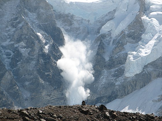
Avalanche simulator landslide test rig
The Avalanche simulator landslide test rig was designed by Adrian Walker and was created to bring real-world avalanche and landslide experiments into the laboratory.
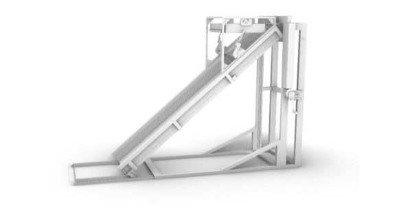
Avalanche simulator landslide test rig
What is the Avalanche simulator? – What does the avalanche simulator do?
The Avalanche Simulator / landslide test rig, was designed and built to conduct experiments in a laboratory or classroom to trial research, practice theories, and teach about avalanches and landslides.
The final avalanche simulator design is shown above in a 3D cad model rendered view and
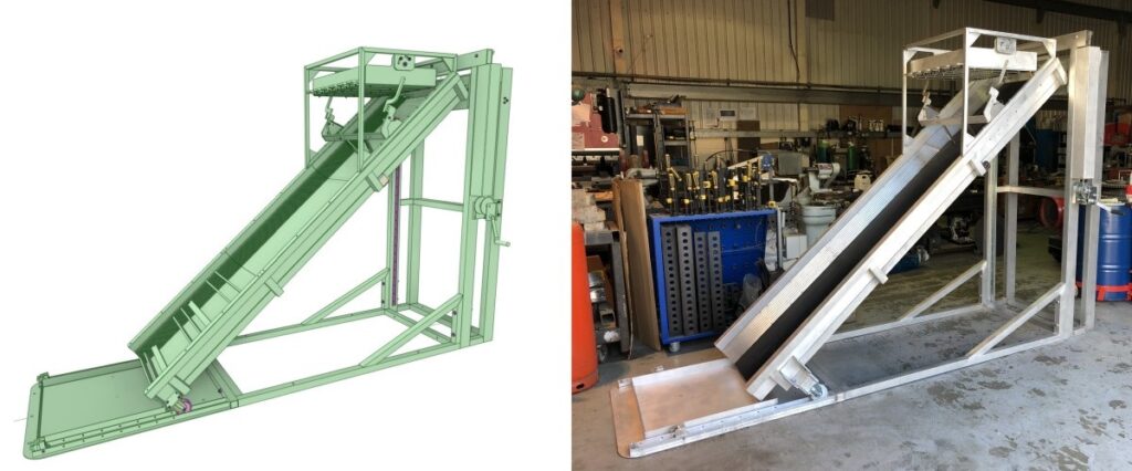
Below left is a 3d cad working model/design. Below right is the finished avalanche simulator in the workshop it was built in.
The avalanche simulator initial brief and rough concept sketches for the client
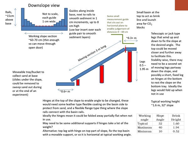
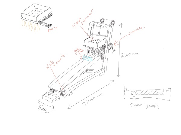
A design like this starts with the initial brief from the client highlighting the required features they would like as shown above left.
This was followed by rough concept sketches and design ideas done by us for the client on the right.
Design scribbles and rough sketches were used internally to scope out the design
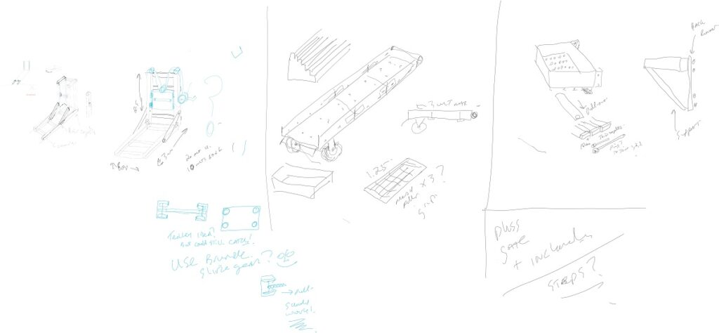
Once the initial concept design was agreed upon and approved by the client. Then the first stage of the design process in-house was to rough out the key design features to get a direction.
This process performed by very rough sketches and scribbles which are for internal use only.
This gives a basic direction for the design and also helps to formulate a rough plan to work from.
Avalanche Simulator 3D cad workings and calculations
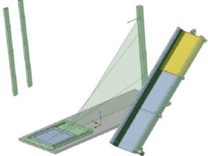
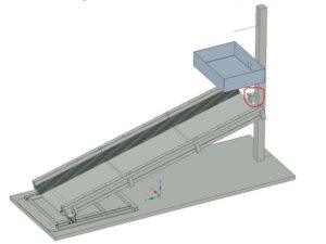
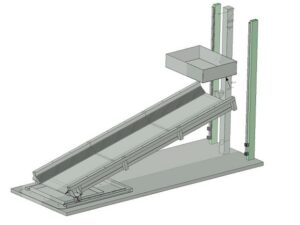
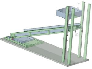
Stages of the 3D cad design process
In some of the 3D cad design stages, you can see the working out the positions and movements of the design
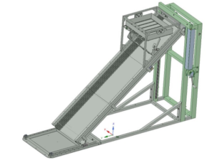
In short, the 3D cad design process starts with some initial 3D cad sketches. Which are then pulled and shaped into the basic features of the 3D design within our 3D software.
Afterward, we then use these basic 3D cad assets to test and find the required positions and extremities of the 3D cad design. Thus helping to find the required pivot points, angles, mounting points, etc.. for the final 3D cad design.
Angle range and movement workings in 3d cad
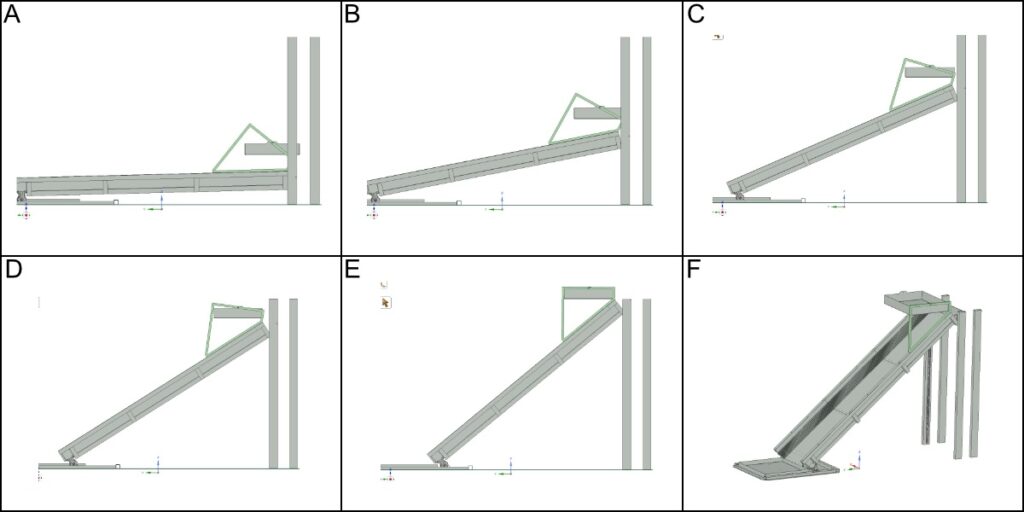
Using the 3D cad design software we are able to look at and move the design through the various stages of its intended use. For the purpose of making sure, there were no issues or restrictions in the intended design.
As a result of this, we can check the areas shown in the images above. Where the movement of the rain-making device is observed through the movement of the chute.
The rainmaker tray needs to stay parallel to the floor whilst the main chute operates through its movement range.
Importing components for use in the 3d cad design
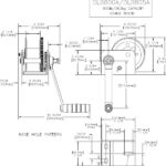
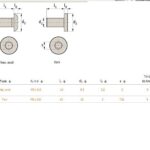
When we use off-the-shelf components in a design, we will try to use supplied data from the suppliers. This enables us to actually place components and see how they will interact and work with the design.
Imported data can come in the form of a 3D cad model which is the best scenario as it can be imported directly into our designs and used within the 3D cad assembly.
Alternatively, as in the case pictured above when we receive the cad data as a 2D cad drawing with limited information, we can still use the data.
We then have to model up the 3D cad part from scratch. However, we would only model up a basic version with the areas required that will affect or interact with the design being most accurately placed.
Avalanche simulator landslide test rig 3D cad design Completed!
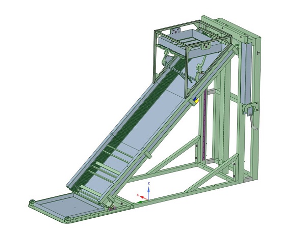
Through all the planning, sketching, thinking, designing, modeling, testing, trial fits, and checks the design has come together as a completed model!
This 3D cad model represents the finished design and is perfectly created.
From this 3d design cad model we can do various things, like:
- Create digital drawings to detail, list and highlight all the features of the design
- Produce the required workshop and manufacturing data in various forms
- Render the design in 3d cad to produce realistic views to assist in client marketing or business proposals
- We can also create video clips and fly-throughs so the client can visualise the design better and get a full view of the design which will also assist in the marketing of the intended products.
Avalanche simulator landslide test rig 3D design conceived
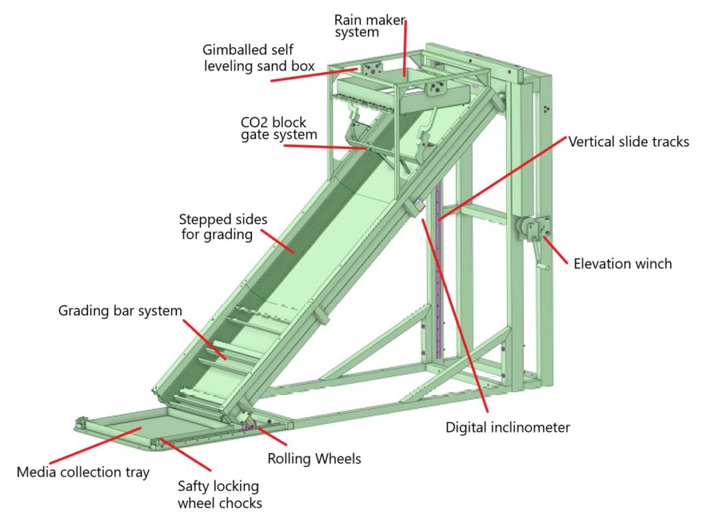
The finished product of the Avalanche simulator/landslide testing rig
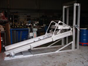
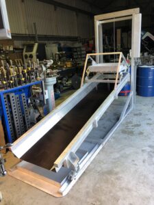
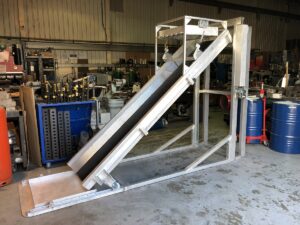
The finished design of the avalanche simulator/landslide testing rig after being manufactured in the workshop, assembled and tested.
Weight testing the design and movement in the avalanche simulator.
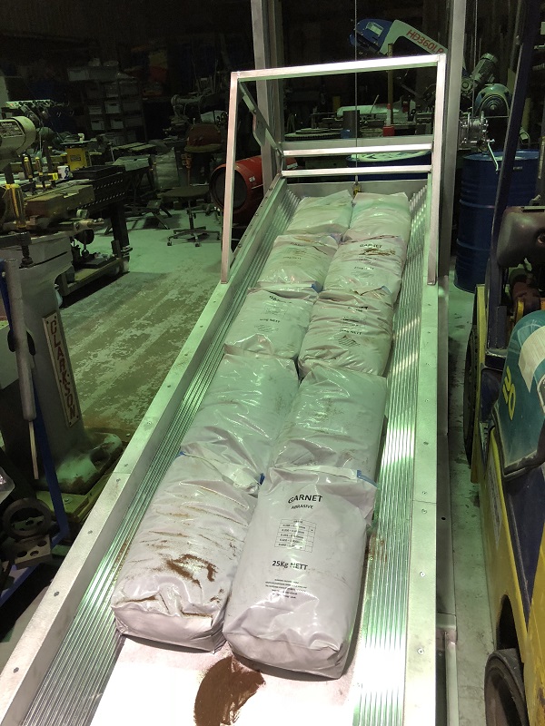
Weight testing the final designed product with 250 kilos of weight. This is so it can be moved through its range of movement and checked for any potential issues.
The Devil is in the detail
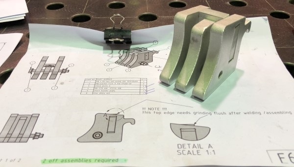
The Devil is in the detail!
Just to highlight a couple of the features of the design:
- Wheel Chocks.
The wheel chocks were designed to add a safety feature. They were able to clip in the lower wheel tracks in set indexed locations. In the event that something were to go wrong at the other end. Then they could restrict the movement should anything go wrong. They were shaped perfectly for the wheel diameter. For the purpose of helping to stop the movement safely. - The rainmaker Device.
For the purpose of showing the detail of the 3D cad design against the finished built device.
In short in the picture below This is a tray that stays parallel to the ground as the main chute is positioned at any angle setting.
Any media could be placed in the tray and when the slides are pulled out the media filters through a mesh screen to rain down onto the media in the chute.
Using a combination of different filter meshes makes and pulling the different slides out enables a variety of tests/experiments to be conducted. I.e the mesh could either slow down or speed up the rate of the media flow, or the masks can be set to scatter the media in different patterns.
The slides are currently set in the picture as grouped in threes, so that when you pull on the handle all three slides come out but this can be changed to suit, so single slides could be pulled if required.
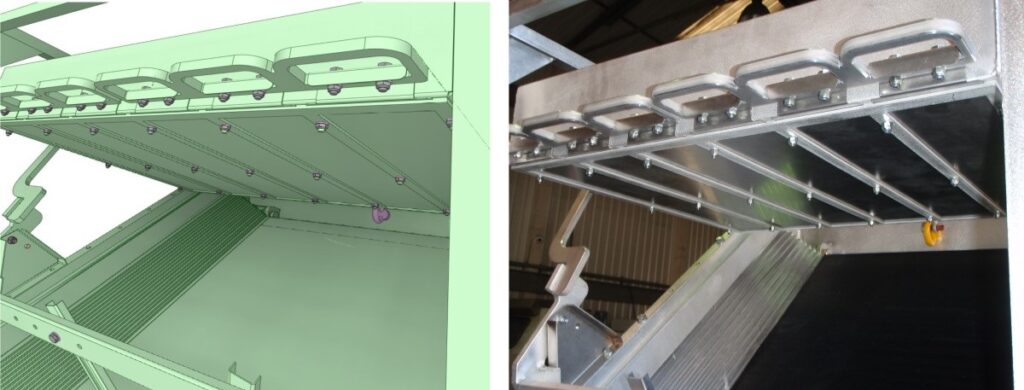
The Avalanche simulator being installed in the Laboratory
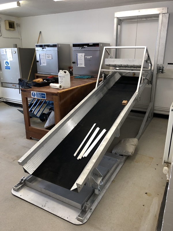
We try to think about all aspects of a design. With this intention, the whole design was planned and made into sections that were located and bolted together. With this in mind, the design was created so it could fit through a small door to the laboratory room where it was being used.
Then the rig was carefully placed in its location and built up ready for use.
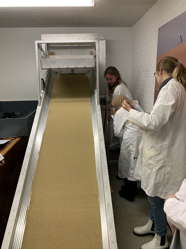
Once the Avalanche Simulator was installed the initial training was given on how the rigs set up and used. Then experiments and tests began.
The chute was loaded with sand for the first test and it is being winched up via the bi-directional hand-operated winch to the required angle as shown above. As a result of this, the angle can then be viewed and checked using the digital inclinometer built into the side of the chute.

So the initial setup was performed. Then a laser scanner was set up on the left seen above on the yellow tripod. For the purpose of scanning the surface of the sand to measure and detect movement during the test experiment.

Then you can see the green laser line scanning the surface of the sand set in the chute. As a result, they will be able to measure and monitor any movement or changes with this process.
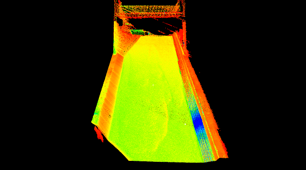
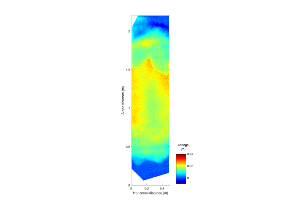
Finally In the picture above and below you can see the laser scanner results for this particular test.
A special Rig designed by Adrian Walker.
What will your project be?
have you got a project or problem to solve? contact Adrian Walker for a solution

