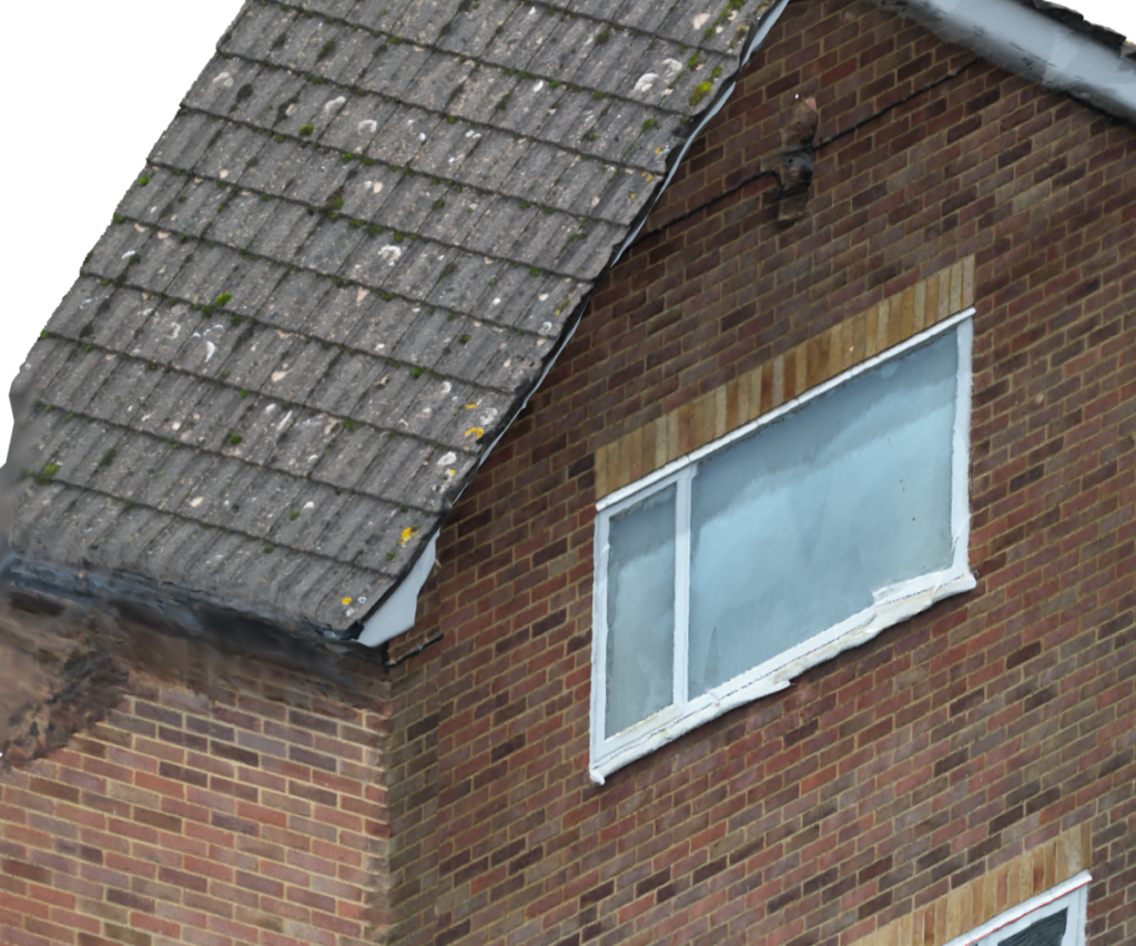
Using photogrammetry to map the front of a house in 3D

Using photogrammetry to map the front of a house in 3D CAD.
Using photogrammetry to map the front of a house in 3D is a good way to get 3D CAD data to work from for a few different reasons.
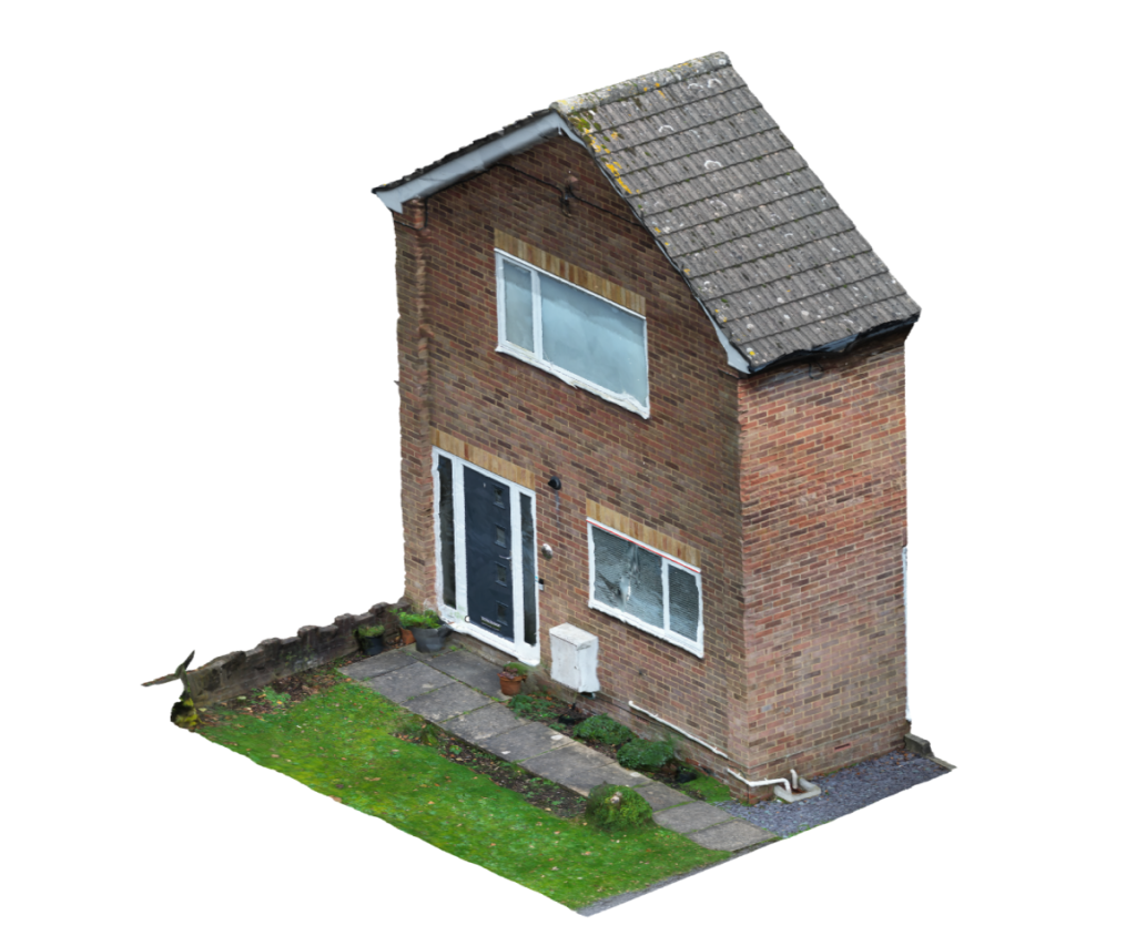
This project is to design a small porch that will be built on the front of the house and we wanted to use accurate imaging of the house in the design to work from and the dimension of, but also to get a 3D representation of the design in place to make sure everyone is happy prior to the building work starting…
Images were taken from a drone flying around the front of the house.
Photogrammetry software was then used to convert the data into usable data.
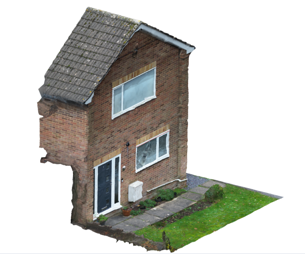
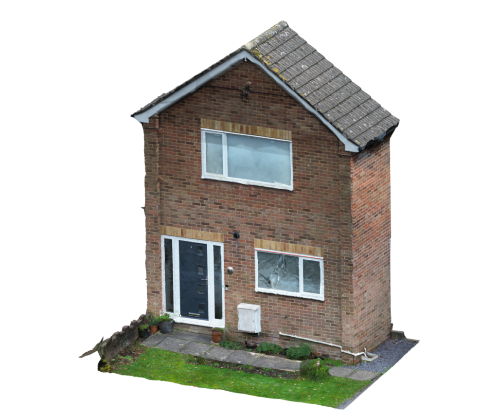
3D CAD was used to render the image you see above which is actually a 3D CAD model!
More details on this project are below……
What is photogrammetry?
Photogrammetry is the art and science of extracting data from a set of photographs.
The photogrammetry process involves taking a series of photos that overlap at different angles of an object, building, structure, or space. Which is then converted into point reference data and subsequently mesh data for 3D CAD
Photogrammetry is used on a wide range of projects including but not limited to:
- Engineering data capture
- 2D and 3D digitizing or templating of areas for projects like tiling
- Architectural work
- Data acquisition
- Analysis work
- Fault-finding and problem-solving
- Mapping and surveying large areas
- Geology and heritage
- Forensic and police investigation
- Rendering 3D Images of an object for various uses
We use both handheld cameras as well as drone-based cameras for data acquisition.
Front of a house in 3D CAD using photogrammetry?
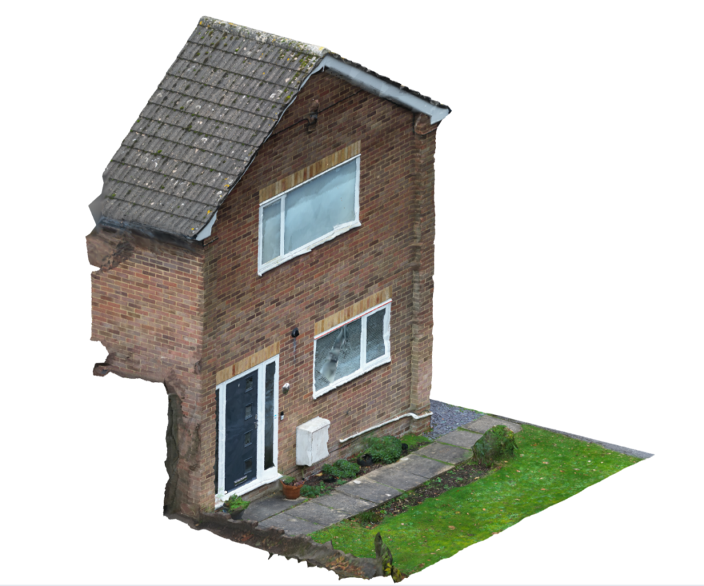
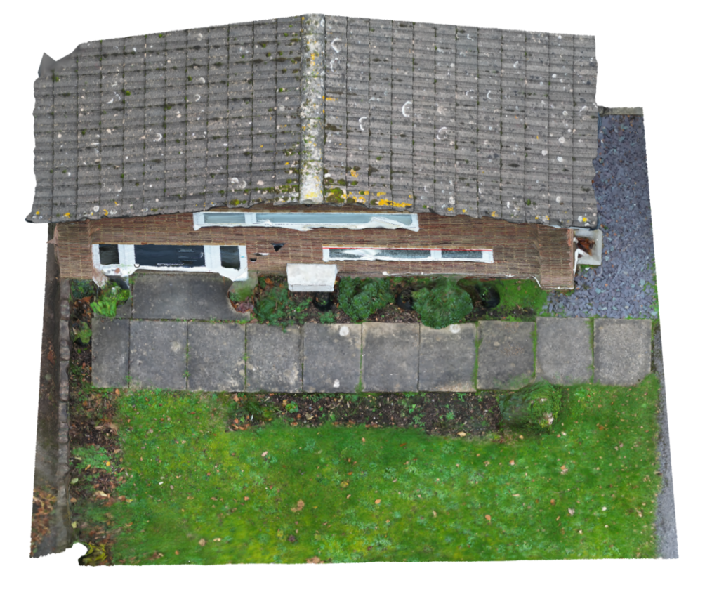
Cad rendered views in 3D CAD using a drone.
In the image above you can see the results of a project that is currently being worked on.
Data was acquired by using a drone flying around the front of the property.
Mesh data was created via the photogrammetry process and brought into the 3D CAD software ready for use.
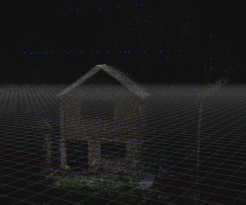
Drone photo collection
A Drone was used to fly around the building’s front, sides, and top to collect the required photographs. In the image above and below you can see the drone camera locations used to get the data. Each blue point is a position where the drone has stopped and taken a photograph.
In the image above you will see what looks like rows of blue dots, This is where the drone has flown across the building at a certain height taking pictures and then the drone is relocated to another height position so it can take another row of pictures.
The building looks ghosted in these two images, however, at this stage, the building in the image is made up of a point cloud with 1000’s to 100’s of thousands of 3D points.
What you are seeing is a collection of small colored points based on their location that have been triangulated from the photos used. This is pinpoint 3D data.
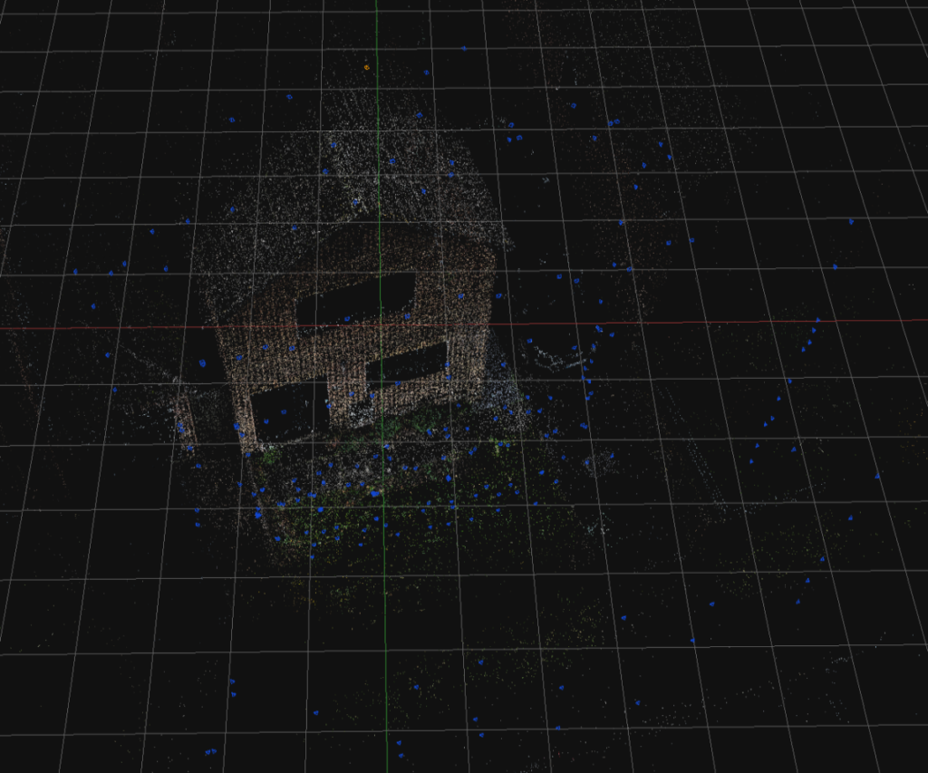
Mathematical algorithms are used by the software to extract precise data points.
Triangulated points are then extracted by the software from the photos taken by the drone.
References from the triangulated points can be used if required to check the photo that was used to acquire them.
Have a look at the video below showing the triangulated data points and how they reference the original photos.
Rendered 3D CAD images and views
The 3D point data is cross-referenced with the photos and a mesh is created.
This is mapped with the images so it starts to become photo-realistic, but it is still a 3D CAD file and usable in 3D CAD.
In the small slideshow above you can see a few different views taken from 3D CAD.
The data acquired can be very large and hard/time-consuming to work with.
So as in this project, only the section I am interested in is used the rest is deleted.
Also, you will notice the image quality is not high in the video and there are some patches in the rendering and the mesh data.
This is to keep it all as lightweight as possible as a data set.
I only need the data required for the project, and in this case, I will be modeling it as a reference and taking some rough dimensions.
Pointless data only bloats the files which adds to time.
What is mesh data?
Mesh data is where surfaces are generated from the point data.
Effectively the points are joined together / connected with small surfaces.
Represented in the images below the mesh data also allows for the colors to be brought through to make it more photo-realistic.
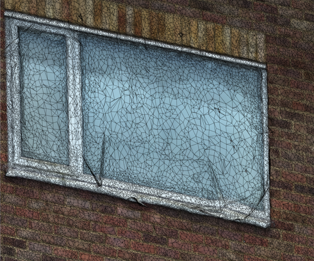
With the mesh data switched on so it is visible on top of the rendering, you can start to see how it is working.
Above is the top window area zoomed in a bit.
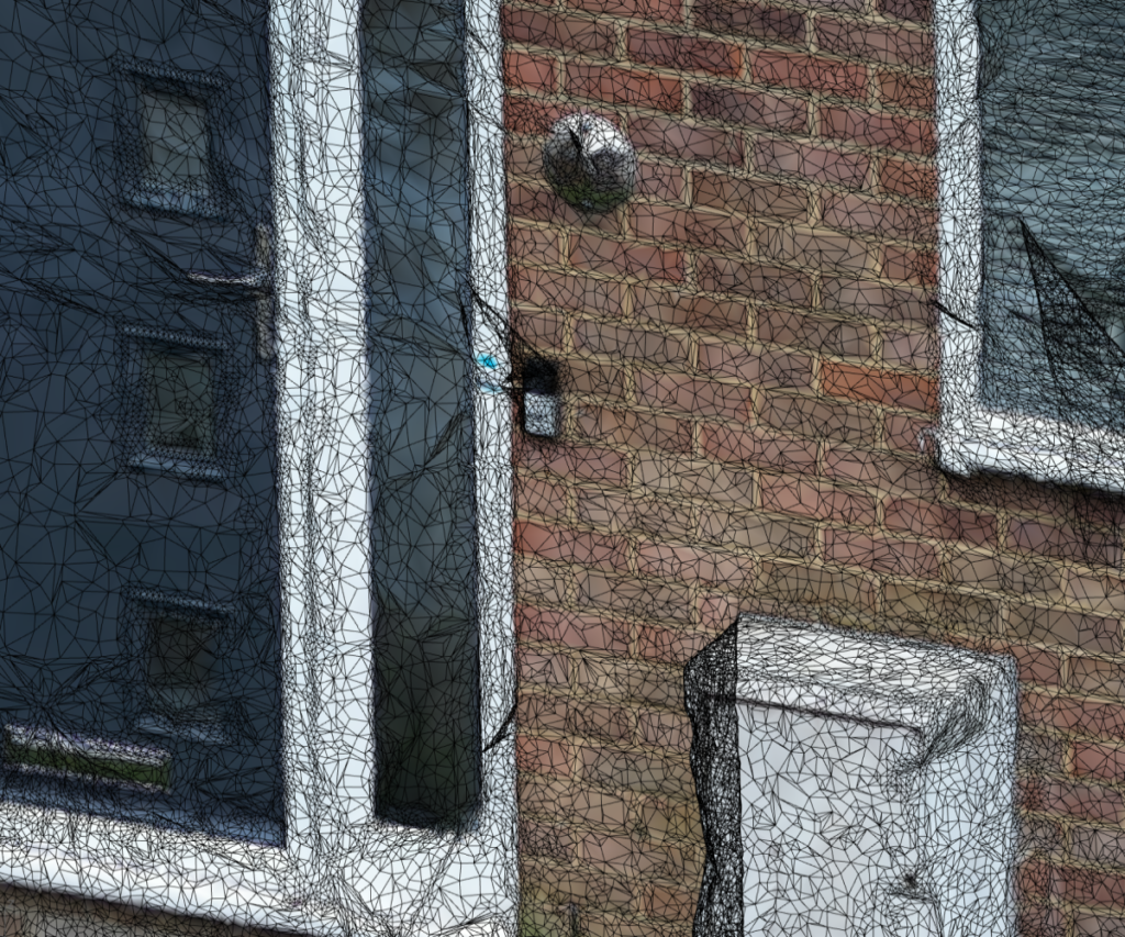
Below is the front door area.
Clearly showing the small surfaces making up the mesh. It looks like a spider’s web!
Weird-looking spikes, bumps, and patches are shown in these two images.
Guesswork is used by the software to fill in any gaps due to missing information or issues with the surfaces being scanned/digitized etc…
This can be improved with more photos and different angles of the point where the photo was taken.
Tweaking the software settings and spending more time to get the best data can all create much better scans, digitizations, and renderings of the property but it really adds to time and cost, so if it is not needed then it won’t be used….
In this project, I am really only interested in the main areas around the door and the ground / paving slabs in front of it, as this is where the newly designed porch will be built, but also want to include the rest of the frontage for future visualisations for the client when the design is ready prior to building.
Working from mesh data in 3D CAD!
Once the scanned data is in CAD it needs to be positioned and re-scaled so it is giving the right feedback and data, then it can start being worked with.
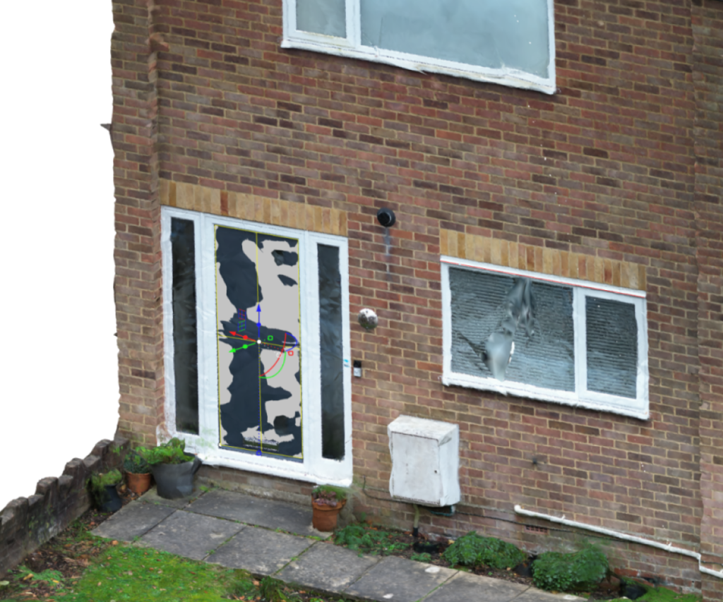
Datumns are set in 3DCAD and used to work from.
Above the image shows a rectangle placed on the front door. This is basically using a cross-section of the mesh data and set in the average position across all the points.
Datum is now set and I can start to work from the data on the design.
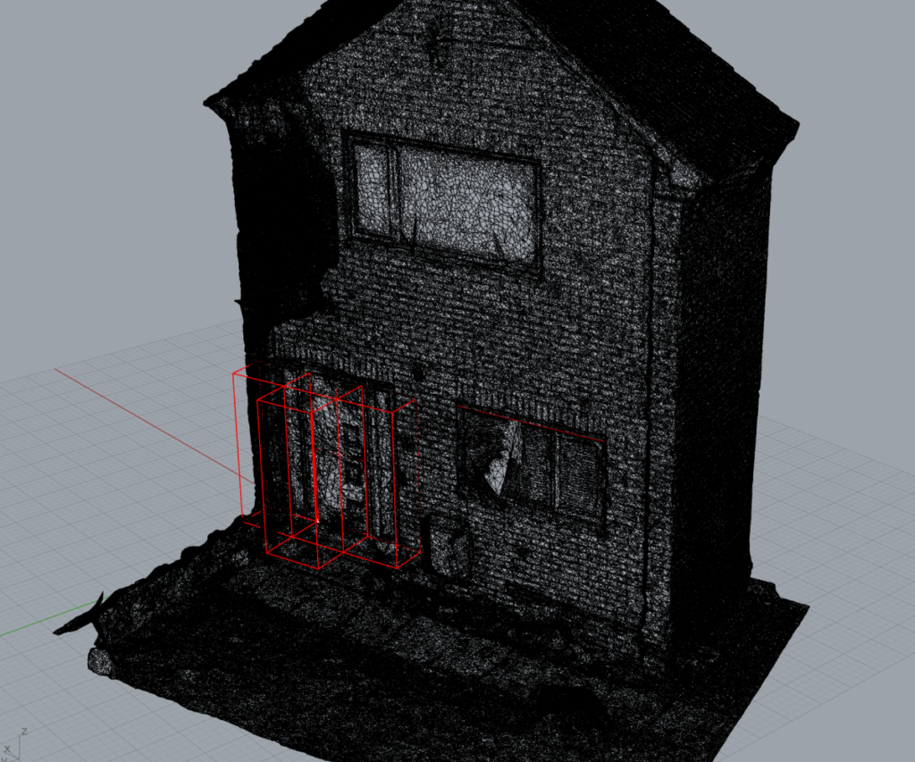
Reducing the display colors to greyscale helps to simplify the view in 3D CAD so I can precisely select the bits of the mesh I need without being confused by the colors.
I then started to add some 3D line blocks purely for reference so I could work off them or around them.
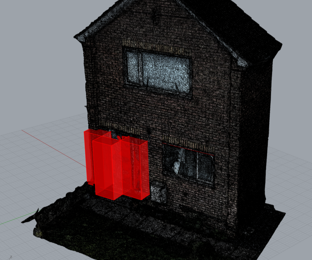
Increasing the display colors in the view in 3D CAD and the 3D blocks made it a bit more visual for better referencing during the design.
A video of what I see in 3D CAD is below.
The design begins in 3D CAD!
With the data acquired, scaled, and set up, we are ready to start the design process!
The project will be shown at a later date when it is completed.
Have you got a project or problem to solve? Contact Adrian Walker for a solution
Detailed design work by Adrian Walker.
What will your project be?
J786

